Saturday, July 7, 2012

Acrylic Water Feeder for Sully


Made this waterer which is designed to aerate the water using a pump waterfall. Also self filling using a float valve. It uses an arduino to aerate for 5 minutes every half hour.

Sully hates the noise and runs away whenever it turns on. But I feel better giving him fresher water.

Wednesday, June 13, 2012

It's been awhile, folks, I'm very sorry to say. I've been pretty busy over the past year with several projects I haven't blogged about. But I'm going to remedy that very soon!

Tuesday, May 24, 2011

3D Printing

I've been working on a project involving numerous small PCBs being deployed in high-traffic industrial areas. I really need enclosures for these devices that can be robust enough to handle some bumps and bruises. Unfortunately, custom enclosures are very Expensive, so I talked my Boss into buying a Thing-O-Matic from Makerbot.com !! YAY!This is a 3D printer. Basically that means it has a CNC platform that moves around while molten plastic is extruded in a pre-defined path. Kind of like at the beach when you dripping wet sand from your fist to make a tower. This technique allows you to make a drawing in some free modeling software like Google's Sketchup and then print the actual object out in real life. In the image above, the printer appears to have just finished printing out a baby rabbit. How cute.

Anywho.
I received the printer a few weeks ago and have been working furiously at assembling the thing, learning how it works, and making some test objects. Here's a video of the Printer cranking out some custom enclosures.


When I say "Cranking out", I really mean "piddling along at a snail's pace," because that's what these 3D printers do. Fortunately, however, there's a conveyor belt on the printer, so you can just set it to print 50 units and then walk away for a couple of hours. When you come back, you'll have a neat little pile of them sitting in front of the printer.

The tech is similar to stereolithography, which is an incredibly expensive process involving a vat of photoactive chemicals and lasers and stuff. The Thing-O-Matic is only about $1300, though, plus there's this really cool community called Thingiverse where you can download designs for all kinds of stuff you might want to make, like the Gothic Cathedral Playset.

Unfortunately, after a couple of weeks of printing, one of the stepper drivers blew out. This appears to be a very un-common problem, but Makerbot was kind enough to replace the device for me, and I should be back up and running any time now.

Here's my Thingiverse page:
You can see the auger I designed and printed for pushing cat food through a pipe.

BRICKSHIELD EXTRAVAGANZA!!!!

So we're calling it the BrickShield now. Don't want to get an angry phone call from the lawyers at Lego, or even worse, some kind of cease and desist.

But it's done! I actually got the PCB back from batchPCB a while back, but have been a little too busy to post about it. Here it is, Start slobbering.

Power select jumpers on the right

You can see it has the Mindsensors NXT port I posted about earlier. This is connected to the TWI pins for "easy" communication with standard NXT devices.

Yellow wire coming from the V+ line

One of the big things I wanted was MORE OUTPUTS, so now we've got simultaneously:
-4 Amplified Digital outs (total of 4 pins on left)
-4 Amplified Motor Outs (total of 8 amplified pins on right)
-4 Servo Ports (below the NXT port)
-Digital lines 0 and 1 available for communication with PC or Radio
-Header for BlueSmirf at top
-Passthrough headers for mounting another shield on top
-Integrated V+ port for higher voltage in drivers
-5V/V+ selection for each via jumper (Servos, Digitals, Motors)
-Optional ICSP pass through for powering additional boards with the 5V line
-Offset header slot on the digital side to allow use with standard perf-board
-Extra 5V an 0V lines by the analog inputs for easy sensor powering

Anybody recognize the LED board on the right?

Below you can see what it looks like with the Libelium Xbee Shield (which I use frequently for RC Projects). If you so choose, you can forget the communication shield on top and just control the Arduino and Brickshield straight from your PC using Arduino Animator.


So I'll be sending these off to a couple of distributors to see if they're interested in selling them. Probably will start with Sparkfun, Makershed or Mindsensors and see if they are interested.
If you'd like to see this as a product you can buy, leave a comment.


New Cabinets = New Workshop

So we're having my friend Josh build custom cabinets for us. All we've got left is the doors to wait for. As soon as he's done, we'll be putting in wood floors, but so far I think things are looking good.
Anywaaaaay.
The real point here is that we had a bunch of old ugly cabinets waiting to be thrown out. But I decided to do what any self-respecting maker would do:


GARAGE WORKSHOP UPGRADE!!!!!!!!!!!!!!


Monday, February 28, 2011

LegoShield Fabrication


Woo-Hoo!
I sent off the newest version of the LegoShield PCB to BatchPCB this weekend, so We'll be getting the first few pieces back in a couple of weeks. At that point, I'll assemble them and see if any distributors are interested in taking part.

I decided to use the official NXT RJ12 (modified phone jack) for the NXT connections, so now you can either plug in a mindsensors multiplexer or plug the device in directly to the shield.


As before, the shield is compatible with the Xbee shield for double-stacking.
Also, there's a blueSMIRF port now, so you can use sparkfun's bluetooth module instead of xbee if you so choose...

Should be interesting!

Monday, February 7, 2011

LegoShield Updates

Sean and I are currently working on improving our Lego Compatible Shield.
Here's an early look at the PCB.

This version will sport:
  • Voltage jumpers rather than switches. I noticed the switches I used on the last version were way underrrated.
  • Can type Capacitor for battery stabilization
  • NXT Header for connecting to the mindSensors NXT host cable. This will make it easy for anyone to connect their arduino to the NXT Sensors.
  • Reset Button Brought to top
  • 5V and 0V Rails next to the Analog In bank
  • BlueSmirf Header for Bluetooth Connectivity (not shown in photo)
  • Pulldown Resistor on the Enable Line
  • VRaw will be connected to external power (don't reverse the leads, folks!)
  • adjustments to the Lego Hole Sizes
Hopefully we'll be ready to send them off for fabrication soon!

Tuesday, January 25, 2011

Meccano is Great

Meccano/Erector is a great prototyping and one-off construction tool.
Here's a device sitting on my desk that I use almost every day.

The mount is resizeable so that any ipod case can slide in and out and be held in place only by friction. This allows me to quickly insert/remove the Ipod before I head home from work.
The back also has a vertical slider so that the viewing angle can be changed.


I enjoy the look of the newer, more industrial looking meccano pieces.

Wednesday, February 24, 2010

Lego RC with Xbee


I've had a conundrum for a while. How to control my RC projects with a ready-made, swappable controller and power board. Many of my recent projects are Lego based, but some are not. My objectives were:

CONTROLLER:
Dual Analog
Dials
Buttons
Toggle
Extra outputs to allow expansion (serial to LCD screen)
Vibration
9V Powered

MOTOR SHIELD:
More outputs than other motor shields
Use XBee devices.
No tunneling
Hot swappable without reconfiguration
Make as an Arduino shield (to avoid reprogramming)
Servo Outputs
PWM (analog motor) outputs
Digital Outputs
Outputs should be amplified
Integrated trimpots and switches for easy configuration
Technics (Lego) hole compatibility

I set off designing the controller board first. I ordered some components from Sparkfun and got the rest from my local electronics store (Elliot Electronics for those of you in Tucson). Some of the components are from DigiKey as well

I based this design on the atmega 328 surface mount board. I built it from the ground up as a non-shield design, but it's basically an arduino without the USB interface.

Normally I use BatchPCB available through Sparkfun.com to make my PCBs, but this time I tried PCB-Pool. That's why the board looks different.

The output from this board (over XBee) will always be the same. Short packets sent out in API mode to whatever remote device is attached to the other Xbee unit. For convenience sake, I used the Xbee API mode library located here : http://code.google.com/p/xbee-arduino/
Thanks Andrew!!!!


After I got the code working all Peachy-like. I started on the other end of the project. The motor shield


I figured by using some clever programming, i could leverage the existing servo and PWM outputs into a ton more. Using a shift register and some switch logic, I expanded the outputs enough to get:
4 PWM Motor Ports
4 Digital Output Ports
4 Servo Ports
TX and RX unaffected on pins 0 and 1
an enable port (pin 13) to avoid startup jittering

So far I haven't had a chance to mount it into an actual project, but I've got a couple projects at the house waiting to be powered up. As you can see in the video, though. The outputs work great, and using the Power Functions Kit and some Servo brackets (mindsensors.com). I can get more devices attached than by using NXT!

Sunday, November 8, 2009

FreePoint SMT Video

I took a video of the surface mounting of a Freepoint Micro board. It's amazing how fast I work...

Several of the pads are for unnecessary components, which is why they're not filled in.

Sunday, August 2, 2009

Rocket Chute Deployment

I have a friend who does model rockets as a hobby. He was looking at getting an off-the-shelf deployment module for adding a parachute to his project. I mentioned that we could do it with an arduino and some sensors.
I had him check digikey.com for a cheap altimeter, and we found one for $7, but the lead time was too long. He's moving pretty soon, so we needed an immediate solution. I decided that we could use an accelerometer, and when it reads 0-Gs on the vertical axis, we'd know it was free-falling. (or had ended acceleration)

We set up a timer that would deploy the parachute a given time after the acceleration ends.


The red and blue wires arm the device. These get twisted together after you get the rocket set up. so it won't go off unexpectedly. The device also monitors the nichrome ignition wires. If one of the wires gets broken, you can tell from the LED indicators on the bottom.

Here's the underside of the board. I drew it up in EAGLE and etched it in the shop at work. You can see it's a little on the hablich side, needs a dose of alcohol and it could also use a small redesign. I noticed after I got the software running that a couple of the outputs were configured wrong in the hardware. If I ever make a V2.0, it'll be a little more attractive.

Hopefully we'll be able to test it out next week after I get back from Mexico.

Friday, May 29, 2009

Agitation

I've been etching numerous PCBs at work for various little projects, and one of the annoying parts of etching is the actual etch process. The copper clad board is immersed in Ferrocloric acid in order to etch away the exposed portions of the board. During the etch, the liquid should be agitated in order to achieve maximum saturation. I got tired of jiggling the tupperware around for 20 minutes, so I built an agitator!


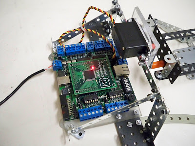
You can see that this project uses the make controller as well as an erector set. I used a HiTec 645MG servo for the agitation.


Here's the video. Rated PG-13 for intense battle sequences and some scary images:

I didn't have anything to etch at the moment, so the video shows the tub with Mountain Dew in it instead. Maybe that would be good for etching designs in teeth...

As you can see, the servo oscillates above and below the horizontal. This ensures that the acid flows both ways.

I made a circuit board for a device we're calling FreePoint. This is the prototype design that's made to plug in as an arduino shield. The final version will be standalone.


Monday, January 26, 2009

Dr. Claw First Run

Well, I got the claw hooked up to my software. Here's the video. I also uploaded it onto youtube, where the quality really sucks, btw.


Now I've got to write some extra-custom software that will allow me to navigate to coordinates and manipulate objects. I also plan to integrate the Wii remote after that using the C# library. Shouldn't be too tough.

You'll notice that the shoulder joint isn't running yet. I'll be adding a geared stepper motor to the base (which already has the gears integrated as shown in a previous blog). I'll also need to make the shoulder a bit sturdier and add a servo reverser before that joint works.

The music is a new song I'm working on with Fuzil.

Saturday, January 24, 2009

Dr. Claw: Hand of Destruction

I wanted to build something really cool using purely Meccano/Erector components. It's tough to integrate electronics with Meccano, but i wanted to get something robotic. I wanted to make sure also that it was only Meccano. I also wanted it to look really good. Not just stuck together with bubble gum and duct tape. So here's what you get:


... I mean even better looking than this...


So here's what I made:


It's a robotic arm. I modeled it off an industrial robotic arm with 5 degrees of motion. It has base rotation, shoulder, elbow, and wrist rotate as well as wrist tilt. Also has a sweet lookin' claw attached to the end.

Here's a shot of the claw in full vertical extension. You can see that I'm using dual servos at each joint. This will allow me to have plenty of strength to move the (heavy) metal Meccano pieces as well as whatever's in the claw at the time.

Here's a horizontal extension:


Build Details:
The above picture is the rotational base. It is purely Meccano, and rotates quite well. I set it up so that I'll be able to drive it with a stepper motor later on via the gear on the left. The stepper will allow me to drive it to a specific angle for precise movement. I really had to put on my thinking cap to come up with the design above.
Here's the stepper I'll be using:


In order to actuate the arm, I had to attach the servo horns somehow. I made servo links from some steel wire i picked up at ACE. Holy crap that stuff was hard to bend. And I wore out a pair of Diagonal Cutters too. My hand is going to be sore tomorrow.

Getting the wire to couple with the erector set was a challenge too. but i found a way to wrap the wire into some stock meccano "ring terminals." I had to crimp the terminals down and wrap the wire around the post for stability, but it turned out great. I also used some hefty HS-645MG metal gear servos from Hi-Tec. These servos have phenomenal torque.


Probably the most difficult part in designing the arm was figuring out how I'd get the wrist to actuate. The shoulder and elbow were tough, but nothing comparted to the wrist. I must have built 10 different claw configurations, and each one wouldn't work for a different reason. Some weren't stable enough, some couldn't hook up to the servos, some were too heavy, too weak, etc. Finally I came up with the design you see here. I think it's perfect, and it balances well with the rear end of the wrist.


You can see that I used the stock Meccano rubber pads for gripping on the claw.

It's important when working with hobby servos, not to stress the servo horn radially. This can damage the axle of the servo, particularly with the wimpy HS-325HB servos I would be using at the wrist. These servos have "karbonite" inner gears. These gears are tougher than plastic, but don't have the durablilty to withstand much abuse. They're kind of like a nylon material. I decided I'd mount the wrist tilt using dual servos facing inward toward the wrist. This would ensure that there was only a low radial load.

Adding the wrist rotation was even more difficult. I wanted to get at least 520 degrees of rotation for manipulating small objects, but servos only have about 190 degrees at most. I used some stock Meccano gearing and built a servo bracket to mount a drive gear vertically: The smaller gear at the bottom is on a shaft that the claw is bracketed to, making the shaft and claw rotate perfectly. (Sounds easy when it's right in front of you, but this took days to figure out)

Below a shot of the pinchers i tried to use. (Grabber attempt #7). I used Shapelock, which is a great product for prototyping. Unfortunately they turned out to be too flexible for my liking. Plus they went against my goal of a pure meccano build.

Shapelock is a low temperature thermoplastic that can be reheated and reshaped endlessly. It's like modeling clay, but better! Given the correct thickness, they would have been less flexible, but I didn't want to worry about the weight etc.
I stayed pretty true to my goal of using only erector set components, in fact, the only non-meccano parts in my build were:
Linkage Rods.
Servos
Home-made Servo Brackets
6 brass collars
Plexiglass Base (seen in indoor shots above)
make controller
So there it is: DR CLAW. A pure meccano build that's sturdy, functional, and fairly attractive.
Feast your eyes.
I also built an external power supply for driving all these crazy servos. The next step will be to hook this sucker up to my make controller and write the software to control it. Fortunately, thought, i think that will be the easy part. I'll try to take some videos during testing.

Sunday, January 18, 2009

Electronics and Meccano (Erector)

Since the dawn of time, mankind has been searching. Searching for the answer to a question that has plaigued us all these years. The burning question that has tormented us since before history will now be answered. The time for answers has come.

How do i get my electronics junk to fit with my erector set???
I've had a love affair with the worlf of Meccano(Erector) for several years now, but the festering issue that has plaigued our relationship is the fact that NO electronics items are designed to jive with the 1/2" hole spacing scheme that meccano is known for.
For rapid prototyping, Meccano just can't be beat. You can build virtually anything with all the little premade mechanical parts, brackets, gears, and hardware included in the sets. I love building the models that come with the kits, but it is always more satisfying to build something yourself. From scratch. And why would you build anything unless it moved on its own. This necessitates servos, sensors, microcontrollers, motors etc. The problem is that none of these devices is hole-compatible with Meccano. The other problem is that there are relatively few places where you can find brackets for these devices, and NOBODY makes these brackets for Meccano. After scouring the internet for solutions, I decided to take matters into my own hands.

The biggest culprit in the war for hole-compatibility is the dreaded servomechanism. Hobby servos are designed with an unusual spacing that makes them practically unusable with your meccano set. Therefore I decided that I would make my own using plexiglass and my router.
(I also have a relationship with that particular tool.) You can see the results below

By creating my own bracket, i was able to get perfect hole compatibility with the servo, and thereby mount it on my project.

Next step: Arduino and Make Controller.

Most microcontroller kits have exposed circuitry on the bottom, which can be risky. So the microcontroller bracket serves a dual purpose. First providing necessary shielding from touching metal, and second, providing slick mounting holes.


Arduino and Lithium Backpack from http://www.liquidware.com/.
Now to try out the Servos on this beast:

You can see that by using a combination of bracketry and meccano spacers, i've got a sweet little setup here. The servos fit in perfectly and leave the drive arms exposed at just the right position.


But just what is this that I'm attaching the servos to?
Stay tuned.

Wednesday, December 10, 2008

Optical Interruptor

Heres an example of how to make an optical interruptor for detecting position. This example uses a simple superbright LED and a light sensor. A black flag passes between these and the light change is detected by the microcontroller.

This is a component of the Harness Roller which was designed using C# and make controller for interfacing.

Monday, November 10, 2008

Disruptor Donor

So for all of you who know about the bike project, here's the donor bike. I'm totally stoked.
We got a restored 1977 Harley Shovelhead lowrider.
I am stoked!!!


Sunday, October 26, 2008

Finalized RC Car Photos

Well, here it is, I've got everything assembled and thought I'd throw up some photos of the finished product!


I have to make some adjustments to the guns still, but outside of that, it's all done. I'd still like to add a camera and laser, but the camera is a bit expensive, so I think the project will be shelved for awhile until some extra cash falls from the sky.